1
Fast onboarding
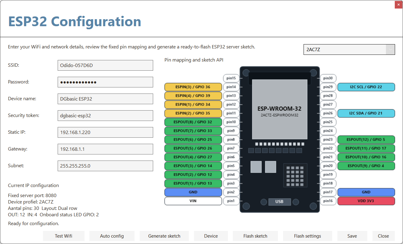
Fill in SSID, password, static IP and token, generate the sketch, and flash your ESP32. After that you can immediately test and switch outputs.

Drive outputs, read inputs, and bring an ESP32 online without building your own networking layer first. DGbasic generates the server sketch, stores the configuration, and now also lets you add your own device profiles with a custom name, image, pin count and GPIO/PIN mapping.
DGbasic turns ESP32 over WiFi from a separate technical project into part of your normal development workflow. That gets you from idea to working hardware much faster. With the new Device button inside ESP32 Configuration you can also store a custom board name, preview image, physical pin count and ESPOUT/ESPIN GPIO/PIN mapping for each board. That keeps DGbasic practical across different ESP32 modules without rebuilding every project from scratch.
Fill in SSID, password, static IP and token, generate the sketch, and flash your ESP32. After that you can immediately test and switch outputs.
You work with fixed DGbasic channels instead of raw GPIO numbers. That keeps examples, projects and service work much easier to follow.
Use the same workflow for LED banks, sensor inputs, relay cards, home automation tests, machine prototypes and compact measurement rigs.
Work with push buttons, LEDs, sensors and relays without first building a complete network architecture. DGbasic keeps the entry barrier low while the ESP32 still remains reachable over WiFi.
Quickly build a test panel for lighting, valves, pumps, shutters or contact sensors. With fixed mapping and Test Wifi you immediately know whether the chain is online and ready to switch.
The workflow is intentionally tight: configure, flash, test, and then immediately switch or read channels from DGbasic.
Open the ESP32 window in DGbasic and fill in SSID, password, static IP, gateway, subnet and token. Those details stay available for later sessions.
Generate the sketch, flash it to the ESP32, and then use Test Wifi to verify that the server is reachable. The built-in LED on GPIO2 also shows that status physically.
Then use ESPOUT and ESPIN as if they were regular DGbasic commands. That lets you build a hardware test, control panel or automation prototype very quickly.
Besides the standard 2AC7Z profile, you can now save multiple custom devices. Each device can have its own dropdown name, image, pin count, GPIO information and ESPOUT/ESPIN mapping.
Many ESP32 boards share the same software base but expose a different physical pin layout. With device profiles you no longer need to remember which board uses which mapping by hand. You simply pick the correct device and DGbasic uses that mapping in the generated server sketch as well.
The ESP32 integration uses a small, clear command set. With it you configure the connection, test the server, and write or read the fixed channels.
Define the fixed IP address and security token for your ESP32 server in one line. This is usually the starting point for a project or test session.
Change only the target address when you want to use another ESP32 and keep the same token.
Check whether DGbasic can reach the ESP32 server. Useful during installation, service and quick diagnostics.
Switch channel 1 through 12 high or low. This drives the fixed ESP32 output mapping for LEDs, relays, signalling or test outputs.
Read channel 1 through 4 for push buttons, contacts, sensor triggers or other digital inputs. That makes it easy to build a control or monitoring setup.
DGbasic abstracts the hardware into fixed logical channels. That lets you keep documentation, examples and projects consistent even when multiple ESP32 devices each use their own physical pin layout.
The generated sketch includes a simple status route for the IDE. While connecting, the built-in LED on GPIO2 blinks; once WiFi and the server are active, it stays on.
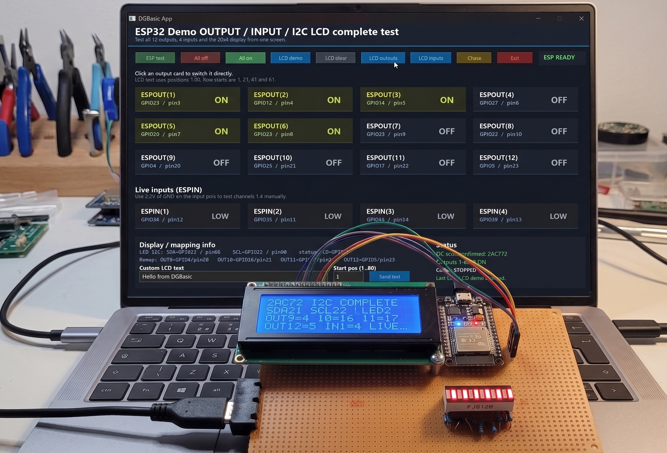
With DGbasic and the ESP32 integration, you can easily build your own control panels. The ESP Dashboard below is an example of what you can create for your home automation: switching lights, reading sensors, and controlling devices, all from your custom-designed interface.
Whether you are building an LED panel, testing a relay board, reading a sensor module or prototyping a small home automation setup: this ESP32 workflow gives you a fast and clean route from DGbasic code to a real WiFi-based installation.